Contributed by: Sciemetric Staff
In the first post of this series, we talked about how the three features that characterize a press-fit operation – Force vs. Time, Distance vs. Time and Force vs. Distance – can be captured and visualized as a digital process signature for accurate and real-time defect detection.
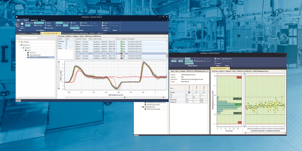
This requires that the press station be equipped with the appropriate sensors and the digital process signature analysis software that can interpret and visualize that sensor data. In this post, we will talk about the specific feature checks that are required to create the process signature, and what they can reveal.
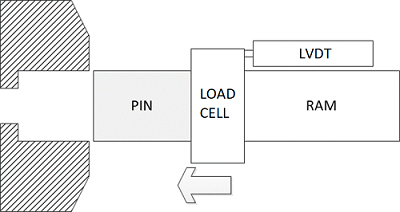
We start by equipping the station with a force transducer to measure the applied force on the press-fit operation, and displacement transducer to measure the movement of the press ram during the operation (image below). The data captured by these devices is interpreted using configurable software applets to determine the values for feature checks. These checks provide a more granular view of those three primary features: Force vs. Time, Distance vs. Time and Force vs. Distance.
In a press-fit operation that is error or defect free, the values for each of these checks will consistently fall into the same range. When they are visualized as a process signature, the signature will be repeatable. This means that the profile or signature of a “good” press-fit will be as distinct as a fingerprint. It doesn’t matter if the press machine in question is hydraulic, servo electric, pneumatic (air over oil), or mechanical.
Any anomaly will show up clearly in the signature as a deviation from this established norm. That makes it easy to determine accurate pass/fail in real time. Quality issues can be detected and action taken before the production line ends up with a pile of bad parts.
GET A QUOTE FOR YOUR PRESS APPLICATION
Common feature checks for force-distance monitoring
Here are the common feature checks for press-fit with the defects that any deviation from the norm may indicate:
- Zero Force (the mean force before the parts come into contact): Worn or misaligned equipment or a worn load cell.
- Alignment Force (measures the maximum force when the parts come into contact and self-align): Misalignment of parts or fixture.
- Minimum Insertion Force (measures the minimum force after alignment and before the end of travel): Broken parts or loose-fitting parts.
- Maximum Insertion Force (measures the maximum force after alignment and before the end of travel): Tight-fitting parts or debris.
- Maximum Force (measures maximum overall force): Improper ram pressure, worn or faulty equipment.
- Insertion Work (measures total work applied to press the components together): Out-of-tolerance or broken parts, debris.
- Insertion Depth (measures maximum displacement): Out-of-tolerance parts, broken parts, debris or worn equipment.
The collective signature data from a press-fit station can also be archived and further analyzed. Hundreds, thousands, even tens of thousands of files can be quickly overlaid to spot trends or patterns that may point to issues that haven’t yet manifested as outright fails.

LEARN MORE ABOUT SCIEMETRIC’S SOLUTIONS FOR PRESS MONITORING