Finding the right limits for your in-process tests is crucial to achieve the highest production yields and minimize, as much as possible, the risks of defective parts slipping through. Manufacturers have long had access to the smart tools they need to quickly optimize their test limits. And yet, many still rely on archaic methods of trial and error, wading through piles of spreadsheets to do manual calculations.
We visited one component company where it was taking weeks to find the correct test limits for an automotive sensor – it even took days for a simple calibration. But if you capture the right data from the test operation that is being monitored, you can eliminate the guesswork and establish the right limits, much faster.
Digital process signatures, or waveforms
Finding the right limits for your manufacturing and production testing starts with digital process signatures, or waveforms. A waveform is a visual representation of everything that happened during a manufacturing operation. Sensors and software capture and visualize hundreds of thousands of data points per cycle for any controlled process –press fitting, leak testing, welding, liquid dispensing, etc. When coupled with analytical software tools, this data, and even all your historic test data that resides in spreadsheets, can be quickly analyzed to show where limits should be set.
Take that component company and its automotive sensor test. We took our sigPOD process monitor and piggybacked it on the test system that was already on the line. The sigPOD PSV™ software was configured to capture feature scalar results and associated waveforms, then analyze each feature while automatically calculating statistically based limits – we automated a cumbersome, manual process that normally took hours to complete.
All this data was then uploaded into our QualityWorX database, where hundreds of waveforms for the parts that were tested were reviewed to further explore the impact of test parameter and limit settings on the results. The correct processing algorithms with associated limits were established within 30 minutes.
In total, it took only a few hours, instead of days or weeks, to optimize this testing process.
In another example, a manufacturer was able to increase its yield by 132 parts a month by using waveforms to understand how it could shorten the cycle time on a break-away torque test.
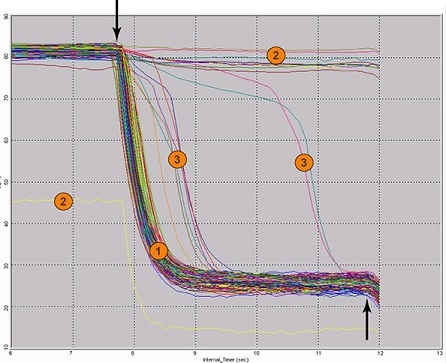
As illustrated in the image to the left, using waveform overlay within Sciemetric's sigPOD PSV™ software, you are easily able to identify and visualize anomalies that help illuminate process issues and/or problems with parts downstream. In the image: Number 1 shows repeatable waveforms of a healthy process producing good parts. The waveforms in Number 2 are the obvious failures, which are usually caught. The waveforms in Number 3, however, are often missed by other monitoring systems because they meet the minimal criteria for a “pass.”
What is the moral of this story?
Have the right tool, for the right job. Otherwise, your team might waste days calibrating or optimizing a test, or fail to see where existing testing cycles can be shortened to boost production yield.
The result is reduced costs thanks to less down time, fewer fails in the field, less stress for your quality team and greater productivity.

