In a two-part post, we will dig into how torque testing can be used as an effective quality control process using digital process signature analysis.
First, let’s run through the basics.
With parts that are meant to turn or rotate, how easy or how difficult it is to initiate that movement can reveal issues with part size or finish, the alignment of parts as they come together, or the presence of any foreign debris that may be interfering with the fit.
We call the angular force required to turn or rotate a part “torque” and it is a common quality assurance test on the production line.
The two common forms of torque testing apply to:
Fastening
Fastening: To ensure a bolt or nut or screw has been installed, not only tightly enough, but properly.
The conventional approach is to simply turn the fastener until a pre-defined maximum torque value is reached. But this single measurement at the end of the operation will not detect if the fastener was mis-threaded or stripped. Typically, a mis-threaded fastener requires fewer rotations than usual and hits that maximum torque value earlier than it should have. Simply measuring for that pre-defined maximum torque value will not detect these clues that indicate a defect.
Rotation
Rotation: To ensure proper function of assemblies that have rotating parts, such as motors, engines or transmissions, with what is commonly known as a torque-to-turn test.
There are two types of torque-to-turn tests:
1) How much torque is required to start a part’s rotation from a stationary position (breakaway torque)
2) How much torque is required to keep it rotating at a constant speed once it starts (running torque)
Just like with the fastener, if too much or too little torque is required versus the torque value of a known good part or assembly, it can indicate a problem. But if the manufacturer is only recording a peak torque value, it doesn’t provide the insight to determine the cause of the problem. Potential issues range from insufficient oil and out-of-tolerance parts, to damaged or defective bearings, or debris that is gumming up the works.

The role of a digital process signature
Whether it is to test a fastener or the rotation of moving parts, for full quality assurance and insight into potential defects, we need to measure more than just maximum or peak torque value. We must capture the full waveform, or process signature, of each operation.
With a signature, what happened through each millisecond of the torque operation – what degree of force was applied, when and for how long – is visualized as a torque-versus-angle signature.
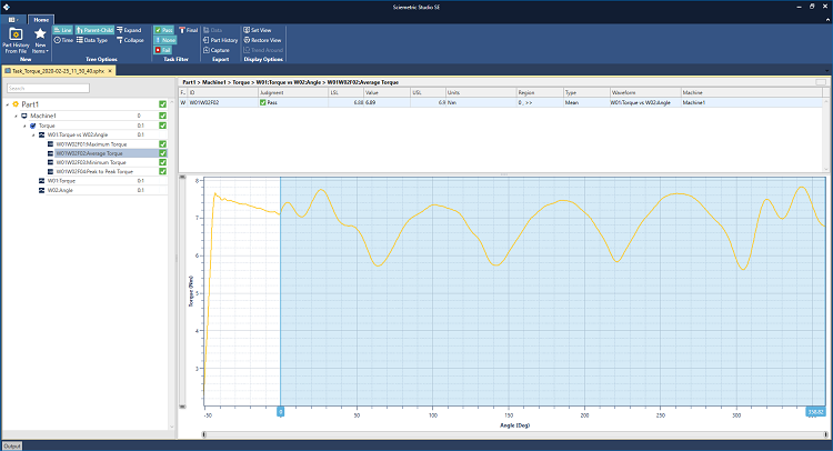
in torque-versus-angle signature to reveal insights into your test.
This reveals the following insights about the torque operation:
⦁ How much torque was required for the process to begin?
⦁ Was the amount of torque applied consistent throughout the entire process and if not, where and when did the variations occur and for how long?
⦁ How long did it take for the desired peak or max torque to be achieved?
A process signature can quickly answer these questions and literally connect the dots that point to a specific issue.
In part 2 of this blog post, we discuss what feature checks to measure for a proper torque test and what issues can be revealed. Read it now: "Torque-to-Turn Testing 101, Part 2: The most important feature checks to identify torque defects".
LEARN MORE ABOUT SCIEMETRIC'S SOLUTIONS FOR TORQUE TEST